 office (979) 703-1874
Cell (979) 218-5226
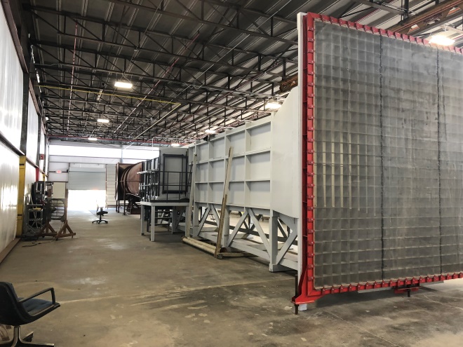
JLMLLM Low Speed Wind Tunnel
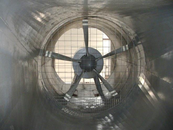
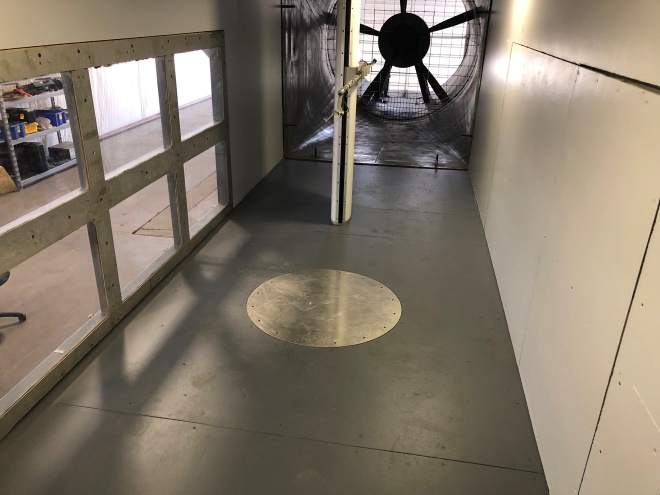
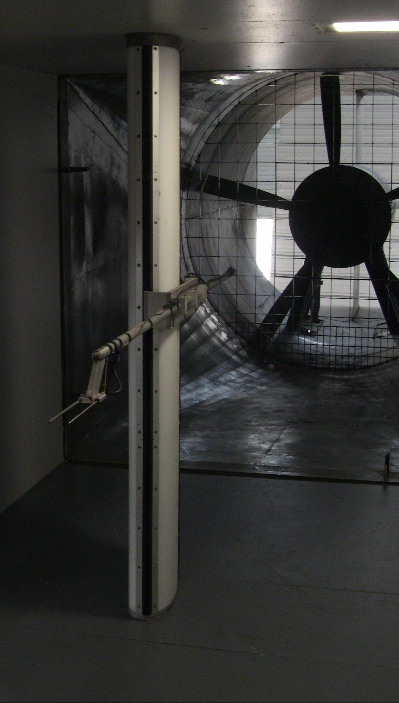
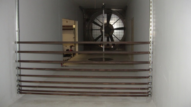
The power section includes 13 ft long diffuser, a 250 hp electric
motor operated at a constant RPM (1185), a five (5) blade propeller
eight (8 ft) diameter with hydraulic blade pitch actuation to
control the wind tunnel wind speed.
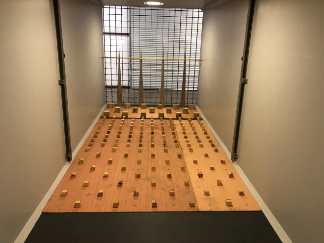
The facility design includes a long section with constant
cross section (32 ft) extending from the nozzle exit to the front of
the test section to help with the development of boundary layer
profiles.
The facility has a 90 mph (40 m/s) maximum speed and a minimum speed
of 20 mph (9 m/s). For
installations including a boundary layer profile the reference speed
at 32 ft (10 m) is between 50-60 mph (23-27 m/s), depending on the
profile selection.
Turbulence levels for a clean tunnel are 1 %.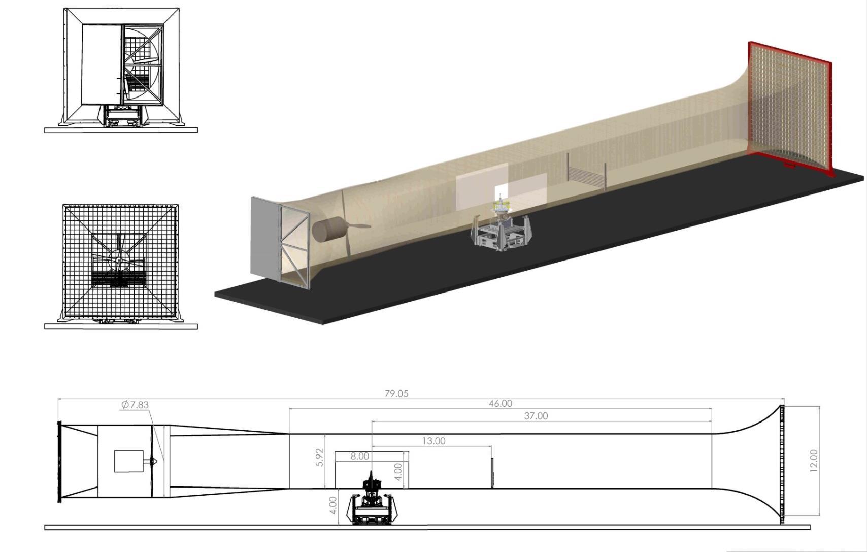
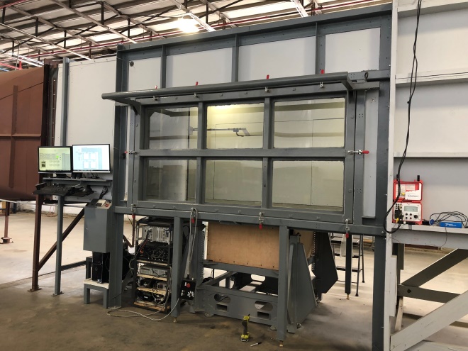
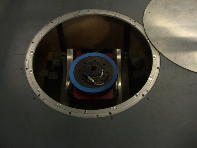
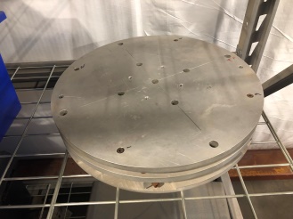
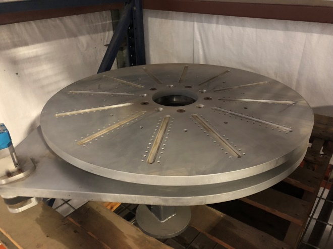
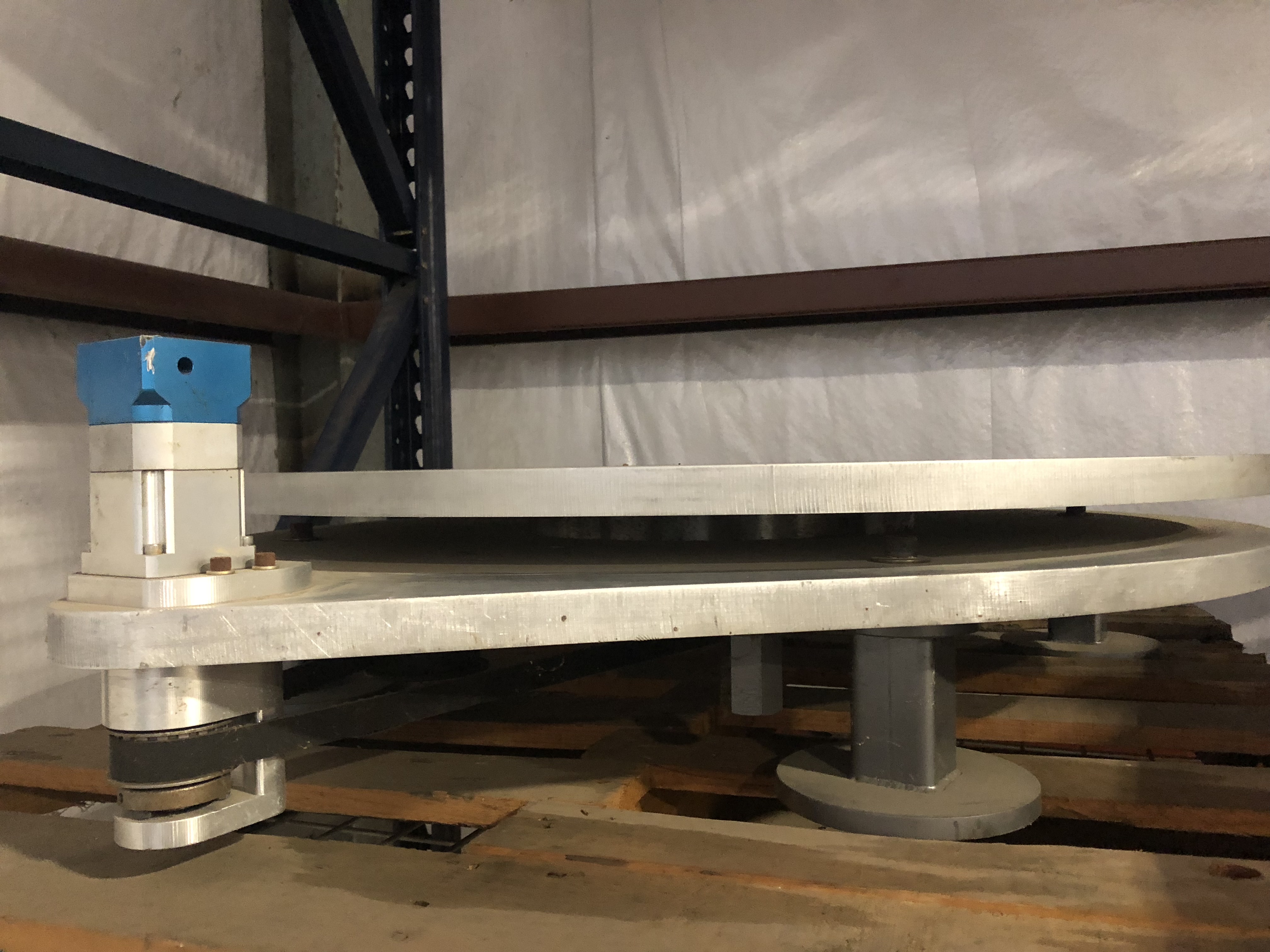
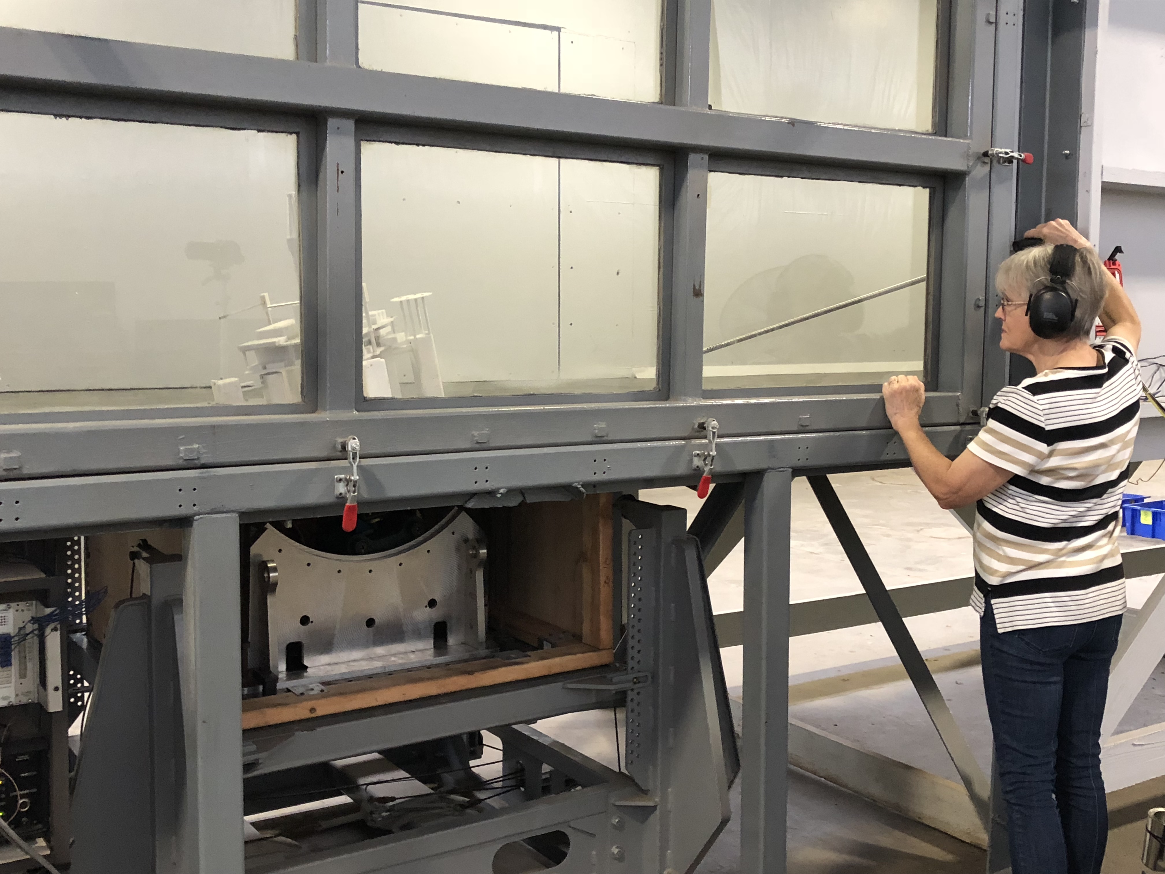
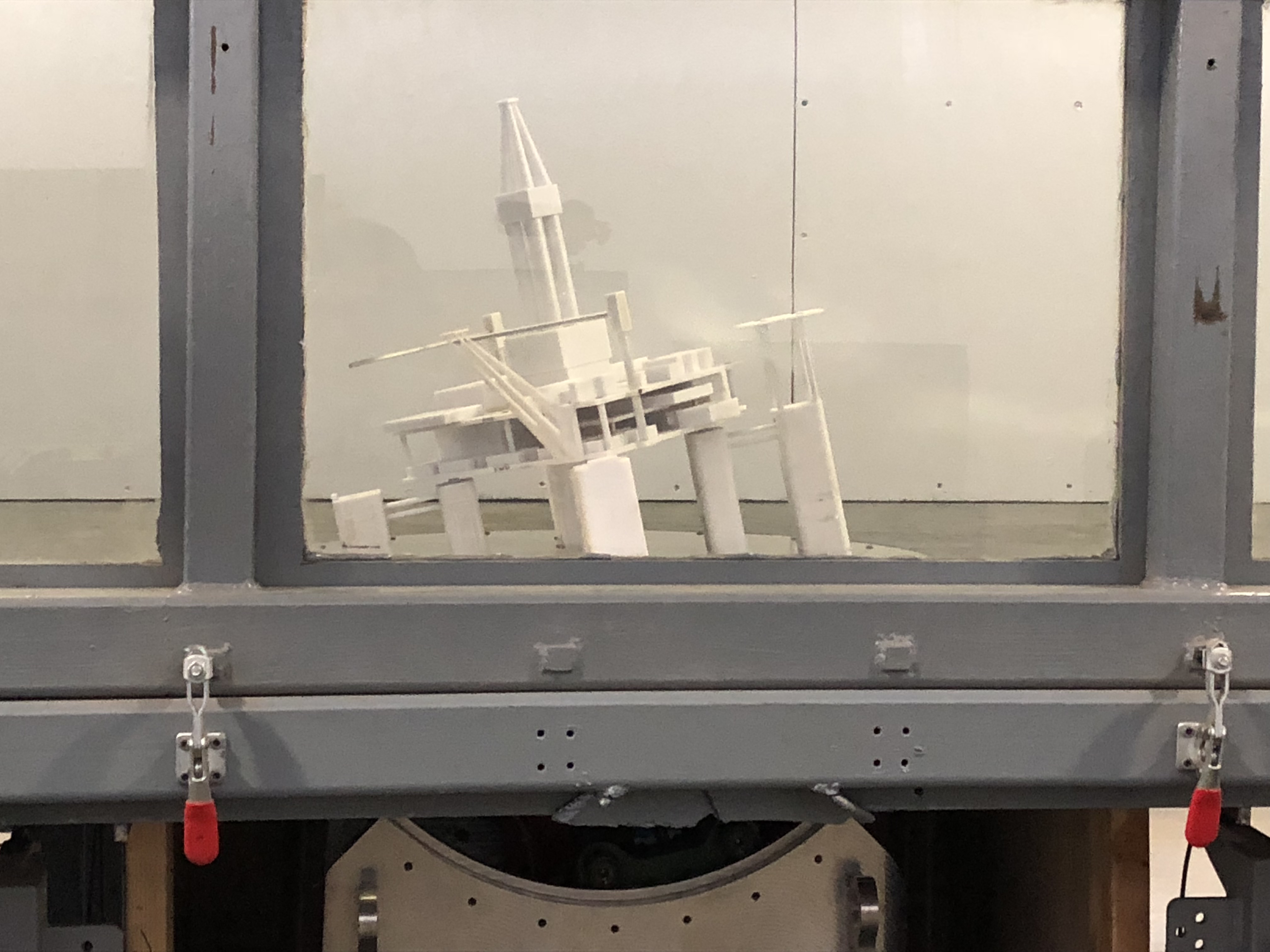
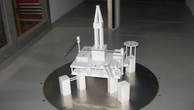
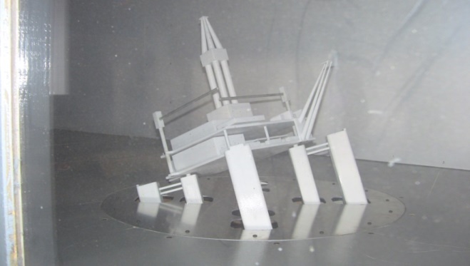
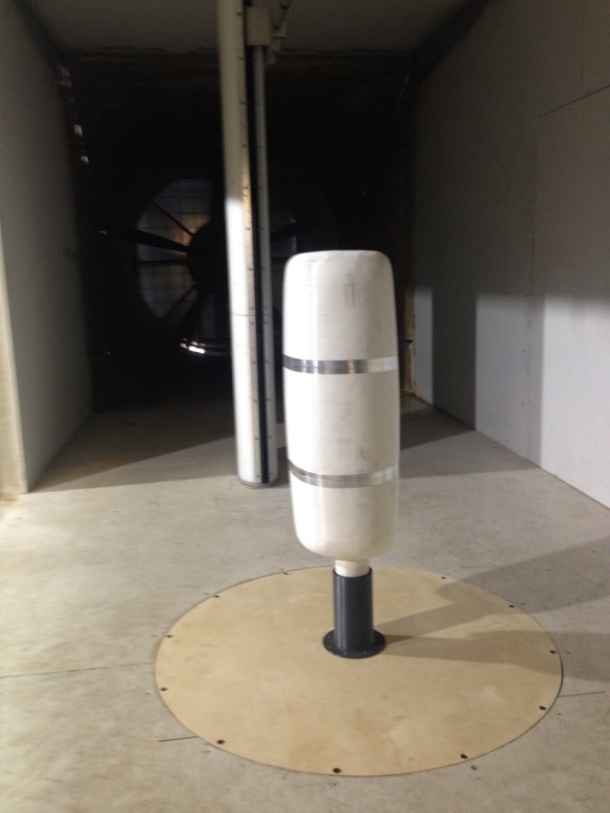
The floor accommodates
a mechanical turntable 28” diameter used for offshore
semisubmersible tests and a 60 in static round table used for larger
setups not requiring the floor to rotate.
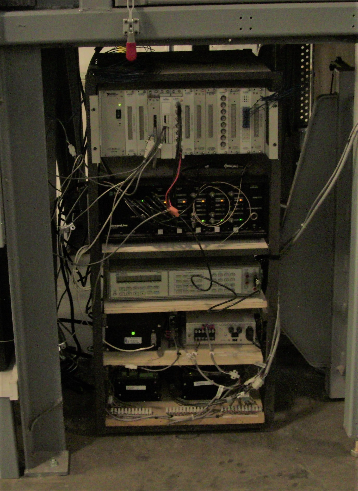
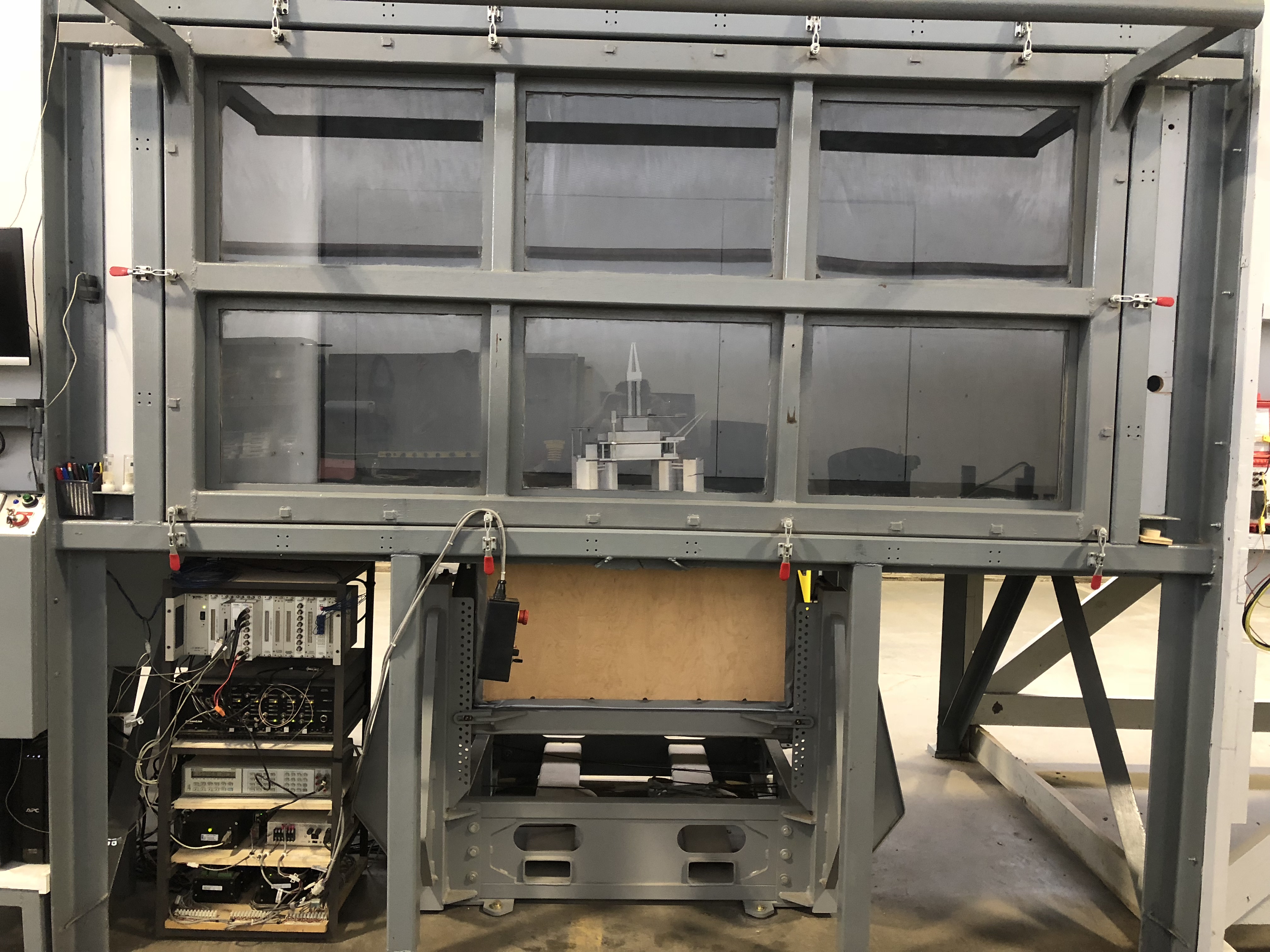
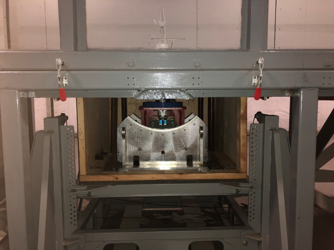
For offshore platforms, the mechanism can change the draft (height) by a range of 6 inches, rotate 0 to 360°, and heel -30 to +30°. The design of the mechanism has a fixed rotation point at floor level and the heel angle is always in the direction of the wind. Typical model scales are 1:196 for floating platforms. All movement is made using stepper motors controlled with a NI LabVIEW code. The in-house developed code includes the data acquisition of the balance loads and wind tunnel conditions, therefore providing all required information for model testing and post-processing.
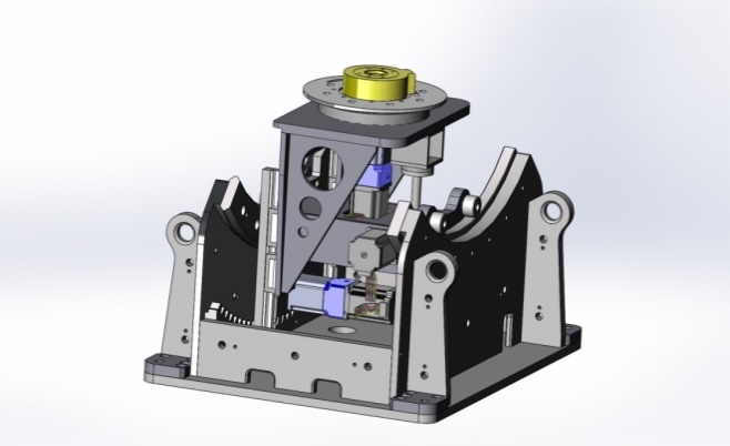
A JR3 force-moment sensor is used to measure the loads and mounted
in between the model and the positioner.
There are two sensors available; the first has a range of 50
lbs in x and y axis, 100 lbs in the z axis and 225 in-lbs in all 3
moments (Mx, My and Mz), the second has a range of 100 lbs in x and
y axis, 200 lbs in the z axis and 450 in-lbs in all 3 moments (Mx,
My and Mz), both of the sensors are 4.5 in diameter and 1.5 in
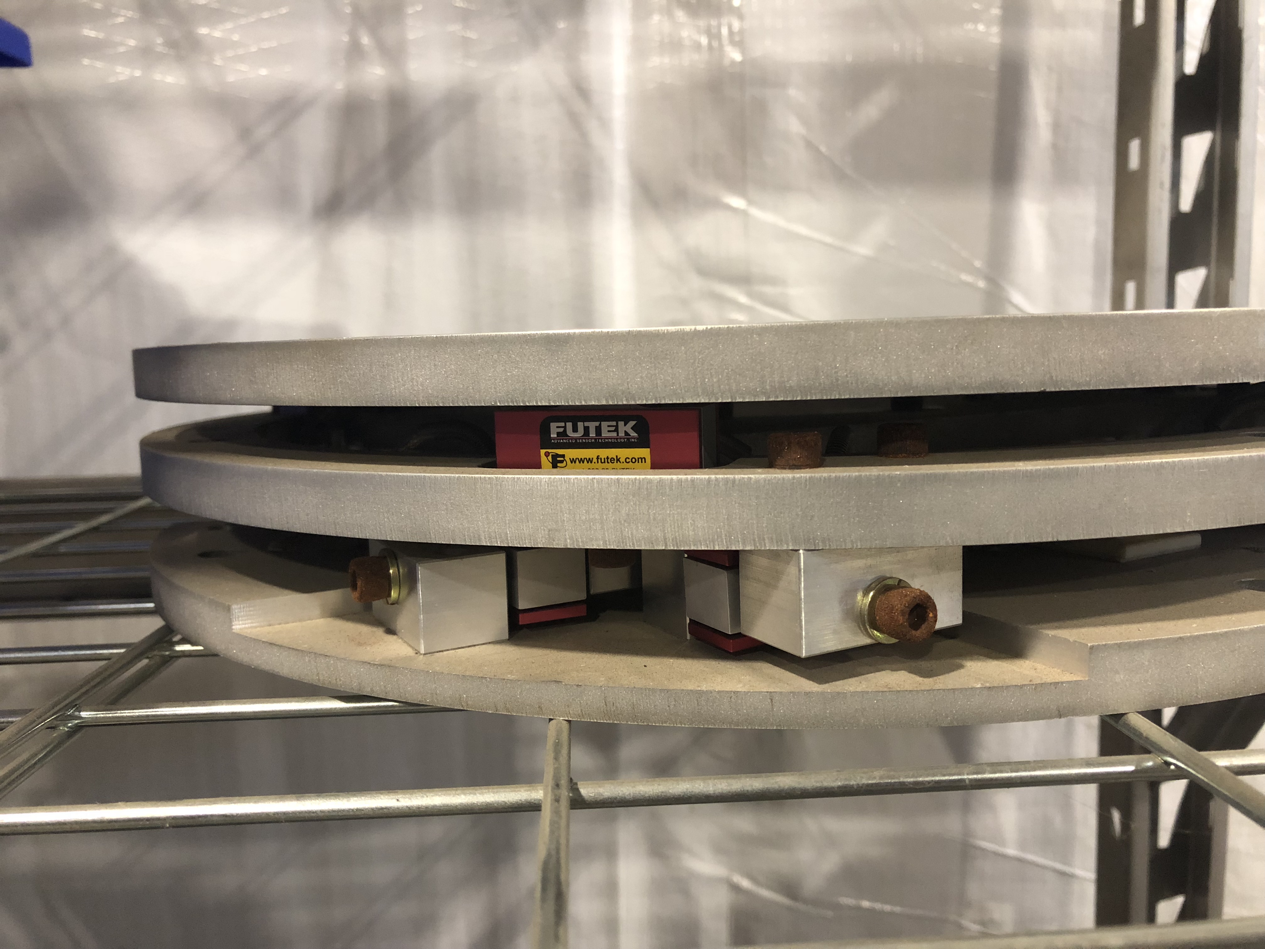
thick. A third balance
system is an in-house developed system that uses 12 load cells.
The system design with three levels measures the 3 forces and
moments, 75 or 150 lbs load cells can be used to change the load
ranges.
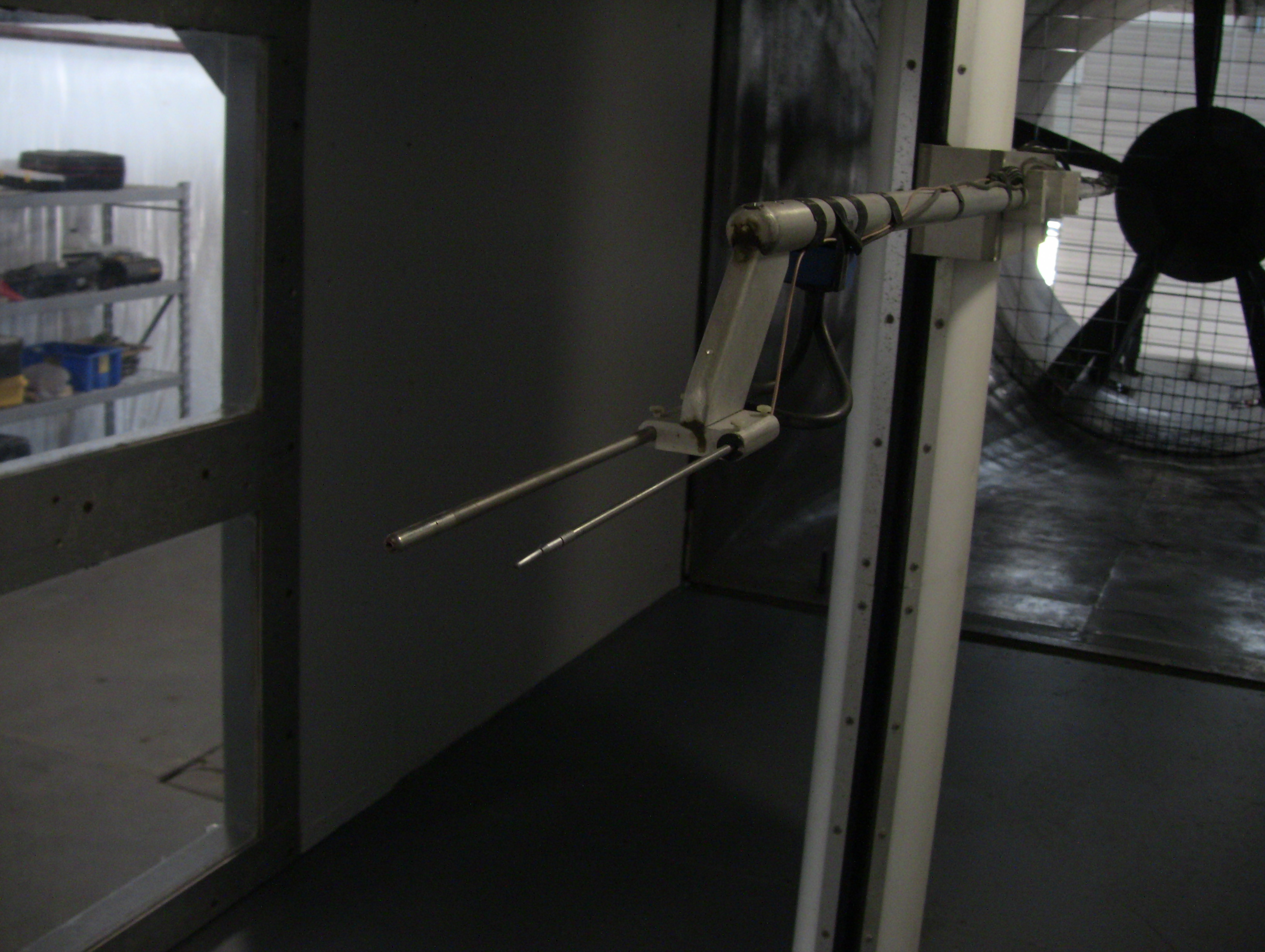
A traversing mechanism is in place behind the test section.
It has a travel of 64 in on the z direction and is controlled
by stepper motors. For
the normal test section survey it carries a pitot static probe and a
single wire CTA probe.
Other probes can be used as needed for a test requirement.
The mechanism is left in place if used to survey the test
section for a test in order to keep a constant blockage effect.
A smoke generator with a 6 ft handheld wand is available for flow
visualization. The wand
can be used from outside through the side wall of the tunnel or by
an operator inside the tunnel.
Other flow visualization techniques including tufts and
tempura paint can be used as required or needed.
Other techniques can be used, but depend on the model and
setup. Cleanup is
always the main concern with some techniques.
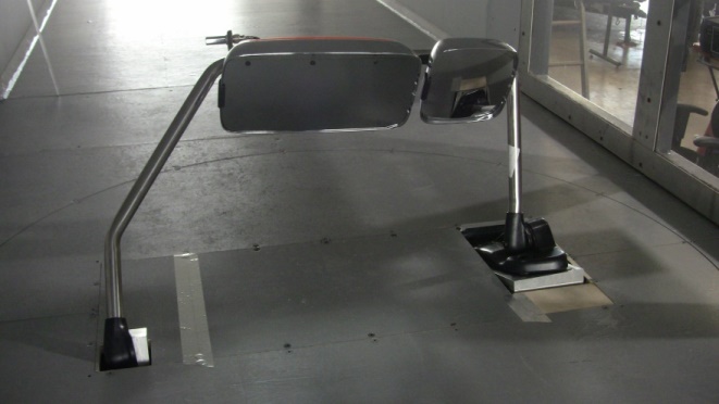
Tests have been successfully performed on offshore platforms and
full scale mirrors. But
like any other wind tunnel the possibilities are only limited by the
test requirements, equipment available and imagination.
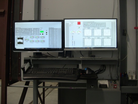
Data acquisition and hardware control software is all done in house
and can be modified to meet test requirements.
All data processing and reduction is done offline using Excel
and can be modified to meet any requirements.
Model and mounting systems can be designed in house using
Solidworks. In house
fabrication capabilities are limited at this time but growing.
A 3 d printer and Small CNC mill are available in house,
along with welding and wood working tools.
JLMLLM Consulting has a good relationship with several local
machine shops which are used to fabricate the parts or models
needed.